Sensors utilize a wide spectrum of transducer and signal transformation approaches with corresponding variations in technical complexity. These range from relatively simple temperature measurement based on a bimetallic thermocouple, to the detection of specific bacteria species using sophisticated optical systems. Within the healthcare, wellness, and environmental domains, there are a variety of sensing approaches, including microelectromechanical systems (MEMS), optical, mechanical, electrochemical, semiconductor, and biosensing. As outlined in Chapter 1, the proliferation of sensor-based applications is growing across a range of sensing targets such as air, water, bacteria, movement, and physiology. As with any form of technology, sensors have both strengths and weaknesses. Operational performance may be a function of the transduction method, the deployment environment, or the system components. In this chapter, we review the common sensing mechanisms that are used in the application domains of interest within the scope of this book, along with their respective strengths and weaknesses. Finally, we describe the process of selecting and specifying sensors for an application.
You have full access to this open access chapter, Download chapter PDF
These keywords were added by machine and not by the authors. This process is experimental and the keywords may be updated as the learning algorithm improves.
Sensors utilize a wide spectrum of transducer and signal transformation approaches with corresponding variations in technical complexity. These range from relatively simple temperature measurement based on a bimetallic thermocouple, to the detection of specific bacteria species using sophisticated optical systems. Within the healthcare, wellness, and environmental domains, there are a variety of sensing approaches, including microelectromechanical systems (MEMS), optical, mechanical, electrochemical, semiconductor, and biosensing. As outlined in Chapter 1, the proliferation of sensor-based applications is growing across a range of sensing targets such as air, water, bacteria, movement, and physiology. As with any form of technology, sensors have both strengths and weaknesses. Operational performance may be a function of the transduction method, the deployment environment, or the system components. In this chapter, we review the common sensing mechanisms that are used in the application domains of interest within the scope of this book, along with their respective strengths and weaknesses. Finally, we describe the process of selecting and specifying sensors for an application.
There are no uniform descriptions of sensors or the process of sensing. In many cases, the definitions available are driven by application perspectives. Taking a general perspective, a sensor can be defined as:
A device that receives a stimulus and responds with an electrical signal.
(Fraden, 2010)
Sensor definitions from a scientific or biomedical engineering perspective broaden the potential types of output signals to include, for example, an optical signal:
A device that responds to a physical input of interest with a recordable, functionally related output that is usually electrical or optical.
(Jones, 2010)
Another common variation, which takes into account the observational element of the measurement, describes a sensor as follows:
A sensor generally refers to a device that converts a physical measure into a signal that is read by an observer or by an instrument.
(Chen, et al., 2012)
Therefore, setting aside the various nuances of domain and application, a sensor simply measures something of interest and provides an output you can do something useful with.
The words sensor and transducer are both commonly used in the context of measurement systems, and often in an interchangeable manner. Transducer is used more in the United States while sensor has greater popularity in Europe (Sutherland, 2004). The blurring of the lines between the exact meaning of sensors and transducers leads to a degree of confusion.
ANSI (The American National Standards Institute) created a standard for Electrical Transducer Nomenclature and Terminology (ANSI, 1975), which defines a transducer as:
A device which provides a usable output in response to a specific measurand.
An output is defined as an “electrical quantity,” and a measurand is “A physical quantity, property, or condition which is measured”.
The National Research Council (NRC, 1995) found, however, that the scientific literature had not generally adopted the ANSI definition (AALIANCE, 2010). Instead, descriptions of transducers focusing on the process of converting a physical quality into a measurable output, electrical or optical, for example, have emerged. One such definition is:
A converter of any one type of energy into another [as opposed to a sensor, which] converts any type of energy into electrical energy.
(Fraden, 2010)
An alternative description is:
A sensor differs from a transducer in that a sensor converts the received signal into electrical form only. A sensor collects information from the real world. A transducer only converts energy from one form to another.
(Khanna, 2012)
However, it is difficult to find consensus on the distinction between sensors and transducers. This problem is exacerbated when the sensor becomes more sophisticated. For example, chemical sensors can be transducers that have been modified to become a sensor e.g. through the use of a sensitive coating covering the sample interface of the transducer. It is clear that strict definitions will always be contentious and driven in part by philosophical differences between engineers and scientists. These differences only hold academic interest when it comes to application development. So while there may be differences in the definitions of sensors and transducers, this has little impact on the ability to utilize sensors in applications. Within this book we use the simple and broad definition that a sensor measures something of interest using a variety of mechanisms, and a transducer converts the output of the sensing processing into a measurable signal. Sensor application developers simply focus on delivering a sensor system that can measure a quantity of interest with the required accuracy. A sensor system usually consists of sensors, measuring and processing circuits, and an output system (Wang, et al., 2011). The key hardware components of a sensor system are described in Chapter 3.
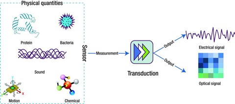
Sensors can be used to measure or detect a vast variety of physical, chemical, and biological quantities, including proteins, bacteria, chemicals, gases, light intensity, motion, position, sound and many others, as shown in Figure 2-1. Sensor measurements are converted by a transducer into a signal that represents the quantity of interest to an observer or to the external world. In this section, we will review the most commonly used sensing techniques for our target domains.
For any given quantity, there is usually more than one form of sensor that can be used to take a measurement. Each sensor type offers different levels of accuracy, sensitivity, specificity, or ability to operate in different environmental conditions. There are also cost considerations. More expensive sensors typically have more sophisticated features that generally offer better performance characteristics. Sensors can be used to measure quantities of interest in three ways:
Mechanical sensors are based on the principle of measuring changes in a device or material as the result of an input that causes the mechanical deformation of that device or material (Fink, 2012). Inputs, such as such motion, velocity, acceleration, and displacement that result in mechanical deformation that can be measured. When this input is converted directly into an electrical output, the sensor is described as being electromechanical. Other possible output signals include magnetic, optical, and thermal (Patranabis, 2004).
The common mechanical and electromechanical sensing approaches as described by the IEEE Sensors Council are shown in Table 2-1.
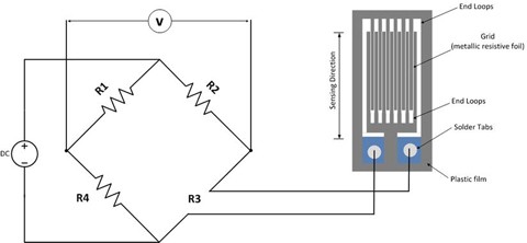
Another common form of strain gauge is based on the piezoelectric (production of electricity when certain materials are subjected to mechanical stress) properties of some semiconductor materials, such as silicon or germanium. These were first used in the car industry during the 1970s, before being applied in other domains, including sports. This form of strain gauge is smaller, has higher unit resistance and sensitivity, and is lower in cost than grid-style strain gauges.
A key problem with strain measurements is that of thermal effects. Changes in temperature cause expansion or contraction of the sensing element, resulting in thermally induced strain. Temperature compensation is required to address the problem and this can be built into the Wheatstone bridge. Piezoelectric strain gauges have even greater sensitivity to temperature variation and greater drift characteristics, which must be compensated for during use by regular recalibration. Strain gauges are used in a variety of sporting and healthcare applications, including clinical dynamometers that measure grip strength (Kasukawa, et al., 2010, Bohannon, 2011).
The name MEMS is often used to describe both a type of sensor and the manufacturing process that fabricates the sensor. MEMS are three-dimensional, miniaturized mechanical and electrical structures, typically ranging from 1 to 100 μm, that are manufactured using standard semiconductor manufacturing techniques. MEMS consist of mechanical microstructures, microsensors, microactuators, and microelectronics, all integrated onto the same silicon chip.
MEMS sensors are widely used in the car industry and, since the early 1990s, accelerometers have been used in airbag restraint systems, electronic stability programs (ESPs), and antilock braking systems (ABS). The recent availability of inexpensive, ultra-compact, low-power multi-axis MEMS sensors has led to rapid growth into customer electronics (CE) devices; MEMS can be found in smartphones, tablets, game console controllers, portable gaming devices, digital cameras, and camcorders. They have also found application in the healthcare domain in devices such as blood pressure monitors, pacemakers, ventilators, and respirators. While there are many forms of MEMS sensors, two of the most important and widely used forms are accelerometers and gyroscopes, which are produced by companies such as Analog Devices and Freescale Semiconductor.
There are five modes of motion sensing: acceleration, vibration (periodic acceleration), shock (instantaneous acceleration), tilt (static acceleration), and rotation. All of these, except rotation, can be measured using accelerometers. It is unsurprising, therefore, that accelerometers have a wide range of applications, from triggering a hard disk protection system as a device is falling, to gesture recognition for gaming. MEMS accelerometers are typically either capacitive or piezoresistive. Capacitive accelerometers are composed of fixed plates attached to a substrate and moveable plates attached to the frame. Displacement of the frame, due to acceleration, changes the differential capacitance, which is measured by the on-board circuitry. Capacitive accelerometers offer high sensitivities and are utilized for low-amplitude, low-frequency devices. Piezoresistive accelerometers contain resistive material bonded to a cantilever beam that bends under the influence of acceleration. This bending causes deformation of the resistor, leading to a change in its resistance relative to the acceleration applied. Piezoresistive accelerometers tend to be more rugged and are used for accelerometers that achieve higher amplitudes and higher frequency response (Piezotronics 1 , 2013, Piezotronics 2 , 2013, Nanogloss, 2009).
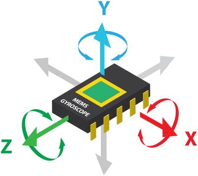
MEMS gyroscopes measure the angular rate of rotation of one or more axes, as shown in Figure 2-3. Gyroscopes can measure intricate motions accurately in free space. They have no rotating parts that require bearings, and therefore lend themselves to miniaturization and batch fabrication using semiconductor manufacturing processes. Almost all MEMS gyroscopes use vibrating mechanical elements (proof-mass) to sense rotation based on the transfer of energy between two vibration modes of a structure caused by Coriolis acceleration. The most popular form of MEMS gyroscope is a tuning fork gyroscope, which contains a pair of masses that are driven to oscillate with equal amplitude but in opposite directions. When rotated, the Coriolis force creates an orthogonal vibration that can be sensed by a variety of mechanisms (Nasiri, 2013). Other forms of MEMS design include vibrating wheel, wine glass resonator (hemispherical resonator gyro), cylindrical vibratory, and piezoelectric. Major manufacturers of MEMS gyroscopes include Robert Bosch GmbH, InvenSense, STMicroelectronics, and Analog Devices. MEMS gyroscopes can be found in smartphones, fall detectors, and games consoles.
Optical sensors work by detecting waves or photons of light, including light in the visible, infrared, and ultraviolet (UV) spectral regions. They operate by measuring a change in light intensity related to light emission or absorption by a quantity of interest. They can also measure phase changes occurring in light beams due to interaction or interference effects. Measuring the absence or interruption of a light source is another common approach. Sensors based on this principle are commonly used in automated doors and gates to ensure no obstacles are present in their opening path. They are widely used in industrial applications for measuring liquids and material levels in tanks or in factory production lines to detect the presence or absence of objects. Optical sensors are also used with stepper motors in applications that require position sensing and encoding, for example, in automated lighting systems in the entertainment industry (Cadena, 2013). Let us now look at the most common types of optical sensors.
Photodetector sensors are based on the principle of photoconductivity, where the target material changes its conductivity in the presence or absence of light. Sensors are sensitive for a given spectral region (range of optical wavelengths) from ultra-violet to infrared. Examples include:
IR sensors come in both active and passive forms, as shown in Figure 2-4. In the active form, the sensor employs an infrared light source, such as a light-emitting diode (LED) or laser diode, which projects a beam of light that is detected at a separate detector (photoelectric cells, photodiodes, or phototransistors). An object that passes through the beam disrupts the received signal at the detector. An alternative configuration is reflectance-based detection, where the source and detector are located in the same enclosure. Light from the IR source is reflected from an object as it moves into the sensor’s field of detection. The amount of light received at the detector depends upon the reflectivity of the object surface. Infrared sensors can be used as counters, proximity sensors (as with automatic doors), or to identify the presence of people or other mobile objects under day or night conditions.
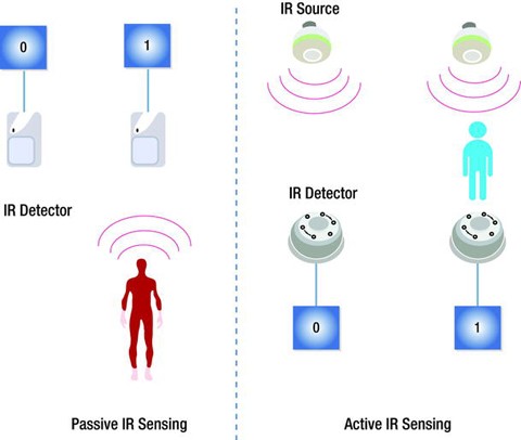
Unlike active sensors, passive sensors do not generate or radiate energy for the purposes of detection. They rely on detected heat from objects, such as human bodies in their detection field. They are commonly used in security lighting around homes and in home security systems to detect intruders (Fried, 2012). They can also be used for ambient sensing applications, an example of which is presented in Chapter 8.
Infrared sensors generally have low power requirements, relatively high immunity to noise, and do not require complex signal processing circuitry. They do, however, have a number of key disadvantages, including the need to be in line-of-sight of the object of interest, a relatively short detection range, and being subject to interference from environmental sources such as sunlight, fog, rain, and dust (EngineersGarage, 2012).
This form of optical sensor uses an optical glass fiber as the sensing element. Multimode fibers with large core diameters (>10 μm) are used for sensor applications. Optical fibers can be coated with materials that respond to changes in strain, temperature, or humidity. The most commonly used fiber-optic sensor types include:
An interferometer is a device used to measure changes in a propagating light beam, such as path length or wavelength along the path of propagation. Generally, the sensor uses a light source such as a laser LED and two single fibers. The light is split and coupled into both of the fibers. The quantity being measured modulates the phase of the optical signal, which can be detected by comparison with a reference optical signal. There are four types of interferometric configuration: Fabry-Perot, Mach-Zehnder, Michelson, and Sagnac. This form of sensor is commonly used for measuring physical quantities, such as temperature, velocity, vibration, pressure, and displacement (Baldini, et al., 2002).
Because optical sensors use light either directly or indirectly for measurements, they have a number of advantages over other forms of sensing. However, these advantages are application-specific, as are the associated disadvantages. Table 2-2 presents the general advantages and disadvantages of optical sensors.
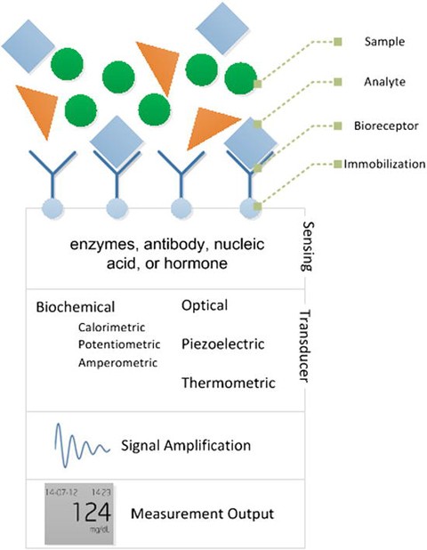
The use of biosensors has increased steadily since Yellow Springs Instruments produced the first commercially successful glucose biosensor in 1975 (Setford, et al., 2005). Biosensors are now available over the counter for a large variety of consumer applications, including cholesterol measurement, fertility monitoring, ovulation status, bacterial infection or exposure (such as Heliobacter pylori), allergies, and STD detection. A report by Global Industry Analysts (GIA) estimates that the biosensors market will be worth approximately USD 16.5 billion by 2017 (PRWeb, 2012). Biosensors have also found niches in domains outside of healthcare. The key biosensor application domains are summarized in Table 2-3.

There are a number of advantages to linear transfer functions. First, it is simple to calculate the measurand value from the electrical output of a sensor and to predict the electrical output based on the measurand value. Second, the sensor offset and sensor slope characteristics are easily read from the transfer function. Third, non-ideal characteristics, such as nonlinearity and hysteresis, can be defined relative to a linear transfer function. A non-linear sensor output can be “linearized” using hardware or software to leverage the advantages of linear sensors (van der Horn, et al., 1998). The traditional hardware-based linearization method often requires manual calibration and precision resistors to achieve the desired accuracy. Modern smart sensors employ less complex and less costly digital techniques to create a linear output. These techniques perform digital linearization and calibration by leveraging the smart sensor’s integrated microcontroller and memory to store the factory calibration results for each individual sensor. The microcontroller can correct the sensor output by searching for the compensation value or the actual linearized output in a look-up table. If memory is limited, calibration coefficients, rather than a full-look up table, are used to construct a linearized output.
Some transfer functions do not approximate well to linear transfer functions. However, they can be approximated using other mathematical functions (Fraden, 2010), including:
where x is the measurand, S is the electrical signal produced by the sensor, A and B are parameters, and k is the power factor. A polynomial function can be used when none of the functions previously described can be applied to describe the sensor transfer function. Second- and third-order polynomials can be described using the following transfer functions:
A third-order polynomial will provide a better fit to the sensor transfer function than a second-order polynomial. However, a second-order polynomial may provide a sufficiently accurate fit when applied to a relatively narrow range of input stimuli.
Nonlinearity, which is often called linearity in datasheets, is the difference between the actual line and ideal straight line. As nonlinearity may vary along the input-output plot, a single value, called maximum nonlinearity, is used to describe this characteristic in datasheets. Maximum nonlinearity is typically expressed as a percentage of span. Nonlinearity can often be affected by environmental changes, such as temperature, vibration, acoustic noise level, and humidity. It is important to be aware of the environmental conditions under which nonlinearity is defined in the datasheet, particularly if they differ from the application operating environment.
Sensitivity is the change in input required to generate a unit change in output. If the sensor response is linear, sensitivity will be constant over the range of the sensor and is equal to the slope of the straight-line plot (as shown in Figure 2-7). An ideal sensor will have significant and constant sensitivity. If the sensor response is non-linear, sensitivity will vary over the sensor range and can be found by calculating the derivative of S with respect to x (dS/Dx).
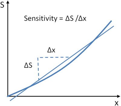
Common sensitivity-related issues include dead-bands and saturation. The dead-band is a specific range of input signals in which the sensor is unresponsive or insensitive. In that range, the output may remain near a certain value (generally zero) over the entire dead-band zone. Dead-band is usually expressed as a percentage of span. The saturation point is the input value at which no more changes in output can occur.
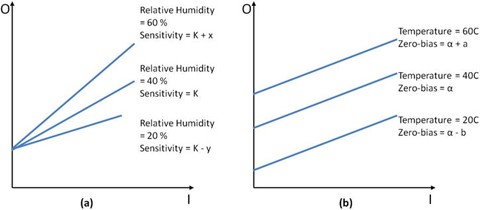
Sensor outputs can be affected by external environmental inputs as well as the measurand itself. These inputs can change the behavior of the sensor, thus affecting the range, sensitivity, resolution, and offset of the sensor. Datasheets specify these characteristics under controlled conditions (such as fixed temperature and humidity, fixed input voltage, and so on). If a sensor is to be operated outside these conditions, it is highly recommended to recalibrate the sensor under the conditions in which it will be used.
Modifying inputs changes the linear sensitivity of a sensor. The voltage supplied to the sensor, Vs, is a common example of a modifying input as it can modify the output range of the sensor, which in turn modifies the resolution and sensitivity.
Interfering inputs change the straight-line intercept of a sensor. Temperature is a common example of an interfering input, as it changes the zero-bias of the sensor. An example of a temperature effect on sensor output is shown in Figure 2-8.
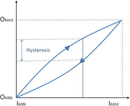
The output of a sensor may be different for a given input, depending on whether the input is increasing or decreasing. This phenomenon is known as hysteresisand can be described as the difference in output between the rising and falling output values for a given input as illustrated in Figure 2-9. Like nonlinearity, hysteresis varies along the input-output plot; thus maximum hysteresis is used to describe the characteristic. This value is usually expressed as a percentage of the sensor span. Hysteresis commonly occurs when a sensing technique relies on the stressing of a particular material (as with strain gauges). Elastic and magnetic circuits may never return to their original start position after repeated use. This can lead to an unknown offset over time and can therefore affect the transfer function for that device.
Resolution, also called discrimination, is the smallest increment of the measurand that causes a detectable change in output. The resolution of modern sensors varies considerably, so is important to understand the resolution required for an application before selecting a sensor. If the sensor resolution is too low for the application, subtle changes in the measurand may not be detected. However, a sensor whose resolution is too high for the application is needlessly expensive. Threshold is the name used to describe resolution if the increment is measured from zero, although it is more commonly described as the minimum measurand required to trigger a measurable change in output from zero.
Accuracy refers to a sensor’s ability to provide an output close to the true value of the measurand. Specifically, it describes the maximum expected error between the actual and ideal output signals. Accuracy is often described relative to the sensor span. For example, a thermometer might be guaranteed to be accurate to within five percent of the span. As accuracy is relative to the true value of the measurand, it can be quantified as a percentage relative error using the following equation: \( \,=\,\frac\times \)
Precision is sometimes confused with accuracy. Figure 2-10 illustrates the key differences between the two. Precision describes the ability of an output to be constantly reproduced. It is therefore possible to have a very accurate sensor that is imprecise (a thermometer that reports temperatures between 62–64° F for an input of 63° F), or a very precise sensor that is inaccurate (a thermometer that always reports a temperature of 70° F for an input of 63° F). As precision relates to the reproducibility of a measure, it can be quantified as percentage standard deviation using the following equation: \(\,=\,\frac\times \)

Error is the difference between the measured value and true value, where true value is a reference to an absolute or agreed standard. There are two forms of error: systematic error and random error.
Systematic errors are reproducible inaccuracies that can be corrected with compensation methods, such as feedback, filtering, and calibration (Wilson, 2004). These errors result from a variety of factors including:
Random error (also called noise) is a signal component that carries no information. The quality of a signal is expressed quantitatively as the signal-to-noise ratio (SNR), which is the ratio of the true signal amplitude to the standard deviation of the noise. A high SNR represents high signal quality. Noise can be measured by recording the signal in the absence of the measurand, or by recording a known measurand several times, then subtracting the known true signal from the measured signal. SNR is inversely proportional to the relative standard deviation of the signal amplitude used to measure precision. Therefore, a noisy signal is also an imprecise signal.
In analytical chemistry, the limit of detection (LOD) and limit of quantification (LOQ) have a particular relevance to noise. The LOD is the lowest quantity of a substance that can be distinguished from the absence of that substance (noise). The LOQ is the limit at which the difference between the substance and absence of that substance can be quantified. LOD is quantified as three times the standard deviation of noise and LOQ is defined as 10 times the standard deviation of noise. True random errors (white noise) follow a Gaussian distribution. Sources of randomness include:
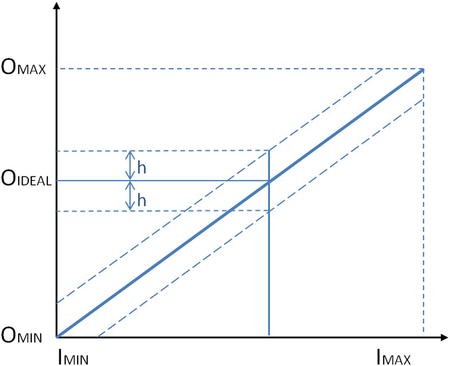
Error bands combine several sensor characteristics (including nonlinearity, hysteresis, and resolution) into a single measure and guarantee that the output will be within a ±h of the ideal straight line. The value “h” is typically a percentage, such as ±5 percent; or a value, such as ± 0.5°C. Figure 2-11 illustrates the concept of error bands around an ideal straight line sensor output. They are advantageous to users as they reduce the number of characteristics that need to be considered when designing an application and are advantageous to manufacturers as they eliminate individual testing and calibrating of each separate characteristic of a sensor.
Statistical characteristics are characteristics that can’t be exactly described by formulas or graphical means. These characteristics describe a summary of numerous measurements taken with a single or multiple sensors. The most commonly used statistical characteristics in sensor datasheets are repeatability and tolerance.
Repeatability is the ability of a sensor to produce the same output when the same input is applied to it. Lack of repeatability generally occurs due to random fluctuations in environmental inputs or operator error.
Tolerance describes the variations in the reported output among a batch of similar elements due to small random manufacturing variations. If a manufacturer reports a tolerance of ±5 percent, it can’t sell any sensors that fall outside of this range.
Dynamic characteristics are time-dependent characteristics of a sensor. Sensor dynamics are less important in applications that have sensor inputs that are constant over long periods of time. Dynamic characteristics can be classified as zero-order, first-order, and second-order systems. The most common dynamic characteristics found in datasheets are response time and dynamic linearity.
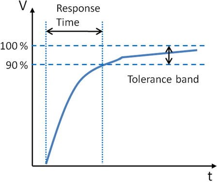
Sensors do not change their output immediately following a change in the input. The period of time taken for the sensor to change its output from its previous state to a value within a tolerance band of the new correct value is called response time (see Figure 2-12). The tolerance band is defined based on the sensor type, sensor application, or the preferences of the sensor designer. It can be defined as a value, such as 90 percent of the new correct value. Response time is commonly defined using time constants in first-order systems (Fraden, 2010). A time constant is the time required by a sensor to reach 63.2 percent of a step change in output under a specified set of conditions. A time constant can be easily estimated by fitting a single exponential curve to the response curve.
The dynamic linearity of a sensor is a measure of its ability to follow rapid changes in the input parameter. Amplitude distortion characteristics, phase distortion characteristics, and response time are important in determining dynamic linearity.
The terms sensor and transducer are commonly used interchangeably, and both devices are encapsulated in sensor systems for a given application. As described in this chapter, a great variety of sensing techniques are available for measuring physical, chemical, and biological quantities of interest. We have briefly outlined the various techniques—mechanical, optical, semiconductor, and biosensing—and have highlighted their respective advantages and disadvantages. We introduced our key sensing domains and described how the various sensor technologies can be utilized within these domains to address problems associated with increased urbanization, global ageing, pollution, and climate change. The role of regulation in driving sensor applications for monitoring air and environmental compliance was also outlined. Finally, sensor characteristics were defined to simplify the process of reading datasheets and comparing performance characteristics of different sensors.
Fraden, Jacob, Handbook of Modern Sensors, 4th ed. New York: Springer, 2010.
Jones, Deric P., Biomedical Sensors, 1st ed. New York: Momentum Press, 2010.
Chen, K. Y., K. F. Janz, W. Zhu, and R. J. Brychta, “Redefining the roles of sensors in objective physical activity monitoring,” Medicine and Science in Sports and Exercise, vol. 44, pp. 13–12, 2012.
Sutherland, John W., An Introduction to Sensors and Transducers, Last Update: 2004, http://www.mfg.mtu.edu/cyberman/machtool/machtool/sensors/intro.html
ANSI, Americian National Standards Institute, “ISA S37.1–1975 (R1982),” ed, 1975.
NRC, (National Research Council) - Committee on New Sensor Technologies: Materials Applications Commission on Engineering Technical Systems, Expanding the Vision of Sensor Materials: The National Academies Press, 1995.
AALIANCE. (2010). Ambient Assisted Living Roadmap, Broek, Ger Van Den, Filippo Cavallo, and Christian Wehrman, Eds., vol. 6, IOS Press, http://ebooks.iospress.nl/volume/aaliance-ambient-assisted-living-roadmap/volume/aaliance-ambient-assisted-living-roadmap
Khanna, Vinod Kumar, Nanosensors: Physical, Chemical, and Biological. Boca Raton: CRC Press, 2012.
Wang, Ping and Qingjun Liu, Biomedical Sensors and Measurement, Berlin Heidelberg: Springer-Verlag, 2011.
Fink, Johannes Karl, “Mechanical Sensors,” in Polymeric Sensors and Actuators, Hoboken, Massachusetts, Wiley-Scrivener, 2012, pp. 131–138.
Patranabis, D, Sensors and Transducers, 2nd ed. New Delhi: PHI Learning Pvt Ltd, 2004.
Kasukawa, Yuji, et al., “Relationships between falls, spinal curvature, spinal mobility and back extensor strength in elderly people,” Journal of Bone and Mineral Metabolism, vol. 28, (1), pp. 82–87, 2010.
Bohannon, Richard W., “Literature reporting normative data for muscle strength measured by hand-held dynamometry: A systematic review,” Isokinetics and Exercise Science, vol. 19, (3), pp. 143–147, 2011.
PCB Piezotronics 2 . “Sensing Technologies used for Accelerometers”, 2013. http://www.pcb.com/Accelerometers/Sensing_Technologies.asp , 2013.
Nanogloss. “What is a MEMS Accelerometer?”, http://nanogloss.com/mems/what-is-a-mems-accelerometer/#more-190 /mems/what-is-a-mems-accelerometer/#more-190, 2009.
Nasiri, Steven, “A Critical Review of MEMS Gyroscopes Technology and Commericalisation Status”, InvenSense, Santa Clara, http://invensense.com/mems/gyro/documents/whitepapers/MEMSGyroComp.pdf , 2013.
Cadena, Richard, “Electromechanical Systems,” in Automated Lighting: The Art and Science of Moving Light in Theatre, Live Performance, Broadcast and Entertainment, Burlington, MA, Elsevier, 2013.
Fried, Limor. PIR Motion Sensors, Last Update: April 27th 2012, http://www.ladyada.net/learn/sensors/pir.html
EngineersGarage. “Infrared Sensors or IR Sensors”, http://www.engineersgarage.com/articles/infrared-sensors?page=3 /articles/infrared-sensors?page=3, 2012.
Udd, Eric, “Fiber Optic Sensors - An Introduction for Engineers and Scientists,” in Pure and Applied Optics vol. 2013, Udd, Eric and William B. Spillman, Eds., 2nd ed. Hoboken, New Jersey: John Wiley & Sons, 2011.
Lee, Byeong Ha, et al., “Interferometric Fiber Optic Sensors,” Sensors vol. 12, pp. 2467–2486, 2012.
Morendo-Bondi, Maria C., Guillermo Orellana, and Maximino Bedoya, “Optical Sensor-- Industrial, Environmental and Diagnostic Applications,” in Chemical Sensors and Biosensors Wolfbeis, O. S., Ed., Berlin Heidelberg, Springer-Verlag, 2004, pp. 251–278.
Baldini, Francesco and Anna Grazia Mignani, “Biomedical Fibre Optic Sensors,” in Handbook of Optical Fibre Sensing Technology, López-Higuera, José Miguel, Ed., Chichester, John Wiley & Sons Ltd, 2002, pp. 705–722.
Nihal, Kularatna and B. H. Sudantha, “An Environmental Air Pollution Monitoring System Based on the IEEE 1451 Standard for Low Cost Requirements,” Sensors Journal, IEEE, vol. 8, (4), pp. 415–422, 2008.
Wetchakun, K., et al., “Semiconducting metal oxides as sensors for environmentally hazardous gases,” Sensors and Actuators B: Chemical, vol. 160, (1), pp. 580–591, 2011.
Knott, Barry. Semiconductor Technology - Personal Breathalyzer, Last Update: January 10th 2010, http://ezinearticles.com/?Semiconductor-Technology---Personal-Breathalyzers&id=3511961 /?Semiconductor-Technology---Personal-Breathalyzers%26id=3511961
Gómez-Pozos, Heberto, et al., “Chromium and Ruthenium-Doped Zinc Oxide Thin Films for Propane Sensing Applications,” Sensors, vol. 13, (3), pp. 3432–3444, 2013.
Fraden, Jacob, “Temperature Sensors,” in Handbook of Modern Sensors, Springer New York, 2010, pp. 519–567.
Coey, J. M. D., “Magnetic Sensors,” in Magnetism and Magnetic Materials, Cambridge University Press, 2010, pp. 516–521.
Sze, Simon M. and Kwok K. Ng, “Magnetic Sensors,” in Physics of Semiconductor Devices, Hoboken, New Jersey, Wiley, 2007, pp. 758–764.
AppliedSensor, “Metal Oxide Semiconductor (MOS) Sensors”, http://www.electronics-base.com/images/stories/General_descriptions/Gas%20sensors/Metal_Oxide_Semiconductor_(MOS).pdf /images/stories/General_descriptions/Gas%20sensors/Metal_Oxide_Semiconductor_(MOS).pdf, 2008.
Gyorki, John R., Designing with Semiconductor Temperature Sensors, Last Update: 2009, http://www.sensortips.com/temperature/designing-with-semiconductor-temperature-sensors/ /temperature/designing-with-semiconductor-temperature-sensors/
Racz, Robert. A Novel Contactless Current Sensor HEV/EV and Renewable Energy Applications, Last Update: 28th March, 2011, http://www.digikey.com/us/es/techzone/sensors/resources/articles/a-novel-contactless-current-sensor-hev-ev.html /us/es/techzone/sensors/resources/articles/a-novel-contactless-current-sensor-hev-ev.html
Eren, Halit, “Magnetic Sensors,” in Wiley Survey of Instrumentation and Measurement, Dyer, Stephen A., Ed., New York, Wiley, 2001, pp. 40–60.
EE TImes. “Non-Contact Fluid Sensor - detects liquid through transparent tubing”, http://www.eetimes.com/document.asp?doc_id=1294625 , 2004.
Refaat, Tamer F., et al., “Infrared phototransistor validation for atmospheric remote sensing application using the Raman-shifted eye-safe aerosol lidar,” Optical Engineering, vol. 46, (8), pp. 086001-086001-8, 2007.
Adami, Andrea, Severino Pedrotti, Cristian Collini, and Leandro Lorenzelli, “Development of a pH Sensor with Integrated Reference Electrode for Cell Culture Monitoring,” in Sensors. vol. 162, Baldini, Francesco, Arnaldo D’Amico, Corrado Di Natale, Pietro Siciliano, Renato Seeber, Luca De Stefano, Ranieri Bizzarri, and Bruno Andò, Eds., Springer New York, 2014, pp. 481–485.
Guth, U., F. Gerlach, M. Decker, W. Oelßner, and W. Vonau, “Solid-state reference electrodes for potentiometric sensors,” Journal of Solid State Electrochemistry, vol. 13, (1), pp. 27–39, 2009.
Kokot, Maciej, “Measurement of sub-nanometer molecular layers with ISFET without a reference electrode dependency,” Sensors and Actuators B: Chemical, vol. 157, (2), pp. 424–429, 2011.
Guth, Ulrich, Winfried Vonau, and Jens Zosel, “Recent developments in electrochemical sensor application and technology — a review,” Measurement Science and Technology, vol. 20, (4), 2009.
Banica, Florinel-Gabriel, “Potentiometric Sensors,” in Chemical Sensors and Biosensors: Fundamentals and Applications, Chichester, UK, John Wiley & Sons, 2012, pp. 165–216.
Wang, Joseph and Kim Rogers, “Electrochemical Sensors for Environmental Monitroing: A Review of Recent Technology”, U.S. Environmental Protection Agency, Office of Research and Development, Environmental Monitoring and Support Laborator, http://www.clu-in.org/download/char/sensr_ec.pdf , 1995.
Andoralov, Viktor, Sergey Shleev, Thomas Arnebrant, and Tautgirdas Ruzgas, “Flexible micro(bio)sensors for quantitative analysis of bioanalytes in a nanovolume of human lachrymal liquid,” Analytical and Bioanalytical Chemistry, vol. 405, (11), pp. 3871–3879, 2013.
Carroll, S., M. M. Marei, T. J. Roussel, R. S. Keynton, and R. P. Baldwin, “Microfabricated electrochemical sensors for exhaustive coulometry applications,” Sensors and Actuators B: Chemical, vol. 160, (1), pp. 318–326, 2011.
Janta, Jiří, Principles of Chemical Sensors, 2nd ed. Heidelberg: Springer, 2009.
Setford, Steven J. and Jeffrey D. Newman, “Enzyme Biosensors,” in Microbial Enzymes and Biotransformations. vol. 17, Barredo, Jose Luis, Ed., Totowa, New Jersey, Humana Press, 2005, p. 30.
“Global Market for Biosensor in Medical Diagnostics to Reach US$16.5 Billion by 2017, Accoring to New Report by Global Industry Analysts, Inc”, http://www.prweb.com/releases/medical_biosensors/environmental_biosensors/prweb9242715.htm , 2012.
Yoon, Jeong-Yeol, Introduction to Biosensors - From Circuits to Immunosensors. New York: Springer, 2013.
Lee, Chang-Soo, Sang Kyu Kim, and Moonil Kim, “Ion-Sensitive Field-Effect Transistor for Biological Sensing,” Sensors, vol. 9, (9), pp. 7111–7131, 2009.
Corcuera, José I. Reyes De and Ralph P. Cavalier, “Biosensors,” in Encyclopedia of Agricultural, Food, and Biological Engineering, Heldman, Dennis R., Ed., New York, Marcel Dekker Inc., 2003, p. 121.
Wang, Joseph, “Electrochemical Glucose Biosensors,” Chemical Reviews, vol. 108, (2), pp. 814–825, 2008.
Peng, Bo, et al., “Evaluation of enzyme-based tear glucose electrochemical sensors over a wide range of blood glucose concentrations,” Biosensors and Bioelectronics, vol. 49, (0), pp. 204–209, 2013.
Durmus, N. Gozde, et al., “Acoustics Based Biosensors,” in Encyclopedia of Microfluidics and Nanofluidics, Li, Dongqing, Ed., Heidelberg, Springer, 2008, pp. 15–24.
Ho, Clifford K., Alex Robinson, David R. Miller, and Mary J. Davis, “Overview of Sensors and Needs for Environmental Monitoring,” Sensors, vol. 5, pp. 4–37, 2005.
Inajima, Tsuyoshi, Takashi Hirokawa, and Yuji Okada. Japan Draws Curtain on Nuclear Energy Following Germany, Last Update: 2012, http://www.bloomberg.com/news/2012-09-14/japan-draws-curtain-on-nuclear-energy-following-germany.html /news/2012-09-14/japan-draws-curtain-on-nuclear-energy-following-germany.html
Schwela, Dietrich, “Air Pollution and Health in Urban Areas,” Reviews on Environmental Health, vol. 15, (1–2), pp. 13–42, 2000.
Watt, Louise. China Pollution: Cars Cause Major Air Problems in Chinese Cities, Huffington Post, http://www.huffingtonpost.com/2013/01/31/china-pollution-cars-air-problems-cities_n_2589294.html /2013/01/31/china-pollution-cars-air-problems-cities_n_2589294.html, 2013.
Wee, Sui-Lee and Adam Jouran. In China, public anger over secrecy on environment, Last Update: March 10th 2013, http://www.reuters.com/article/2013/03/10/us-china-parliament-pollution-idUSBRE92900R20130310 /article/2013/03/10/us-china-parliament-pollution-idUSBRE92900R20130310
EPA, “List of Designated Reference and Equivalent Methods,” vol. MD-D205-03, ed. Research Triangle Park, North Carolina: National Exposure Reseach Laboratory, 2012, p. 60.
Fine, George F., Leon M. Cavanagh, Ayo Afonja, and Russell Binions, “Metal Oxide Semi-Conductor Gas Sensors in Environmental Monitoring,” Sensors, vol. 10, (6), pp. 5469–5502, 2010.
Kumar, A., H. Kim, and G. P. Hancke, “Environmental Monitoring Systems: A Review,” Sensors Journal, IEEE, vol. 13, (4), pp. 1329–1339, 2013.
Diamond, Dermot, Fiachra Collins, John Cleary, Claudio Zuliani, and Cormac Fay, “Distributed Environmental Monitoring,” in Autonomous Sensor Networks. vol. 13, Filippini, Daniel, Ed., Springer Berlin Heidelberg, 2013, pp. 321–363.
Zhang, C., W. Zhang, D. J. Webb, and G. D. Peng, “Optical fibre temperature and humidity sensor,” Electronics Letters, vol. 46, (9), pp. 643–644, 2010.
Borisov, Sergey M., Roman Seifner, and Ingo Klimant, “A novel planar optical sensor for simultaneous monitoring of oxygen, carbon dioxide, pH and temperature,” Analytical and Bioanalytical Chemistry, vol. 400, (8), pp. 2463–2474, 2011.
Mead, M. I., et al., “The use of electrochemical sensors for monitoring urban air quality in low-cost, high-density networks,” Atmospheric Environment, vol. 70, pp. 186–203, 2013.
Bales, E., et al., “Citisense: Mobile air quality sensing for individuals and communities Design and deployment of the Citisense mobile air-quality system,” in Pervasive Computing Technologies for Healthcare (PervasiveHealth), 2012 6th International Conference on, 2012, pp. 155–158.
Kumar, A., I. P. Singh, and S. K. Sud, “Energy efficient air quality monitoring system,” in Sensors, 2011 IEEE, 2011, pp. 1562–1566.
Korotcenkov, Ghenadii, Sang Do Han, and Joseph R.Stetter, “ChemInform Abstract: Review of Electrochemical Hydrogen Sensors,” ChemInform, vol. 40, (22), 2009.
James, George. Perrier Recalls Its Water in U.S. After Benzene Is Found in Bottles, The New York Times, New York, http://www.nytimes.com/1990/02/10/us/perrier-recalls-its-water-in-us-after-benzene-is-found-in-bottles.html /1990/02/10/us/perrier-recalls-its-water-in-us-after-benzene-is-found-in-bottles.html, 1990.
Czugala, Monika, et al., “CMAS: fully integrated portable centrifugal microfluidic analysis system for on-site colorimetric analysis,” RSC Advances, vol. 3, (36), pp. 15928–15938, 2013.
Cogan, Deirdre, et al., “Integrated flow analysis platform for the direct detection of nitrate in water using a simplified chromotropic acid method,” Analytical Methods, vol. 5, (18), pp. 4798–4804, 2013.
Santini, Silvia, Benedikt Ostermaier, and Andrea Vitaletti, “First experiences using wireless sensor networks for noise pollution monitoring,” presented at the Proceedings of the workshop on Real-world wireless sensor networks, Glasgow, Scotland, 2008.
Maisonneuve, Nicolas, Matthias Stevens, Maria E. Niessen, Peter Hanappe, and Luc Steels, “Citizen Noise Pollution Monitoring,” presented at the 10th International Digital Government Research Conference, Puebla, Mexico 2009.
Radu, Tanja, et al., “Portable X-Ray Fluorescence as a Rapid Technique for Surveying Elemental Distributions in Soil,” Spectroscopy Letters, vol. 46, (7), pp. 516–526, 2013.
Yang, Chin-Lung, et al., “Design and evaluation of a portable optical-based biosensor for testing whole blood prothrombin time,” Talanta, vol. 116, (0), pp. 704–711, 2013.
Girardin, Céline M., Céline Huot, Monique Gonthier, and Edgard Delvin, “Continuous glucose monitoring: A review of biochemical perspectives and clinical use in type 1 diabetes,” Clinical Biochemistry, vol. 42, (3), pp. 136–142, 2009.
Swensen, James S., et al., “Continuous, Real-Time Monitoring of Cocaine in Undiluted Blood Serum via a Microfluidic, Electrochemical Aptamer-Based Sensor,” Journal of the American Chemical Society, vol. 131, (12), pp. 4262–4266, 2009.
McLachlan, Michael J., John A. Katzenellenbogen, and Huimin Zhao, “A new fluorescence complementation biosensor for detection of estrogenic compounds,” Biotechnology and Bioengineering, vol. 108, (12), pp. 2794–2803, 2011.
Wang, Xuefeng, Ming Zhao, David D. Nolte, and Timothy L. Ratliff, “Prostate specific antigen detection in patient sera by fluorescence-free BioCD protein array,” Biosensors and Bioelectronics, vol. 26, (5), pp. 1871–1875, 2011.
Arami, A., A. Vallet, and K. Aminian, “Accurate Measurement of Concurrent Flexion-Extension and Internal-External Rotations in Smart Knee Prostheses,” IEEE Transactions on Biomedical Engineering, vol. 60, (9), pp. 2504–2510, 2013.
Uzor, Stephen and Lynne Baillie, “Exploring & designing tools to enhance falls rehabilitation in the home,” presented at the Proceedings of the SIGCHI Conference on Human Factors in Computing Systems, Paris, France, 2013.
Shyamal, Patel, Park Hyung, Bonato Paolo, Chan Leighton, and Rodgers Mary, “A review of wearable sensors and systems with application in rehabilitation,” Journal of NeuroEngineering and Rehabilitation, vol. 9, (1), pp. 21–21, 2012.
Wei, Yang, Russel Torah, Kai Yang, Steve Beeby, and John Tudor, “Design optimized membrane-based flexible paper accelerometer with silver nano ink,” Applied Physics Letters, vol. 103, (7), 2013.
Metcalf, Cheryl D., et al., “Fabric-based strain sensors for measuring movement in wearable telemonitoring applications,” presented at the IET Conference on Assisted Living, London, UK, 2009.
Mass, Fabien, Julien Penders, Aline Serteyn, Martien van Bussel, and Johan Arends, “Miniaturized wireless ECG-monitor for real-time detection of epileptic seizures,” presented at the Wireless Health 2010, San Diego, California, 2010.
Brown, L., et al., “A low-power, wireless, 8-channel EEG monitoring headset,” in Engineering in Medicine and Biology Society (EMBC), 2010 Annual International Conference of the IEEE, 2010, pp. 4197–4200.
Buono, Michael J, Amy Jechort, Raquel Marques, Carrie Smith, and Jessica Welch, “Comparison of infrared versus contact thermometry for measuring skin temperature during exercise in the heat,” Physiological Measurement, vol. 28, (8), pp. 855–859, 2007.
Spulber, I., et al., “Frequency analysis of wireless accelerometer and EMG sensors data: Towards discrimination of normal and asymmetric walking pattern,” in Circuits and Systems (ISCAS), 2012 IEEE International Symposium on, 2012, pp. 2645–2648.
Reaston, P., M. Reaston, and B. Kuris, “Wireless Diagnostics,” Pulse, IEEE, vol. 2, (2), pp. 20–26, 2011.
Jing, Meng, Liang Dong, and Song Liang, “Compressed sensing photoacoustic tomography in vivo in time and frequency domains,” in Biomedical and Health Informatics (BHI), 2012 IEEE-EMBS International Conference on, 2012, pp. 717–720.
Ng, J. H. G., et al., “Design, manufacturing and packaging of high frequency micro ultrasonic transducers for medical applications,” in Electronics Packaging Technology Conference (EPTC), 2011 IEEE 13th, 2011, pp. 93–98.
McCaffrey, C., O. Chevalerias, C. O'Mathuna, and K. Twomey, “Swallowable-Capsule Technology,” Pervasive Computing, IEEE, vol. 7, (1), pp. 23–29, 2008.
National Wellness Institute. “The Six Dimensions of Wellness”, http://www.nationalwellness.org/?page=Six_Dimensions , 2013.
Freescale, “Medical Applications - User Guide”, http://www.freescale.com/files/microcontrollers/doc/user_guide/MDAPPUSGDRM118.pdf#page=44 /files/microcontrollers/doc/user_guide/MDAPPUSGDRM118.pdf#page=44, 2012.
Apple. “Nike + iPod - Meet Your New Personnal Trainer”, http://www.apple.com/ipod/nike/ , 2012.
Continua Health Alliance. “Health & Wellness - Fitness goals will be more easily attainable”, http://www.continuaalliance.org/connected-health-vision/health-and-wellness.html /connected-health-vision/health-and-wellness.html, 2010.
Helmenstine, Anne Marie. How Do Smoke Detectors Work? - Photoelectric & Ionization Smoke Detectors, Last Update: 2013, http://chemistry.about.com/cs/howthingswork/a/aa071401a.htm
Bently, John P., Principles of Measurements Systems, 3rd ed. Singapore: Longman, 1995.
van der Horn, Gert and Johan Huijsing, “Calibration and Linearization Techniques,” in Integrated Smart Sensors: Design and Calibration, Springer, 1998.
Wilson, Jon S., Sensor Technology Handbook. Burlington, MA: Newnes, 2004.